You may already know that MTF is an abbreviation for Modulation Transfer Function. MTF provides a way to objectively measure image sharpness in a practical and repeatable way that also correlates well with subjective perceived image sharpness.
The smallest practical unit for measuring image detail is a line pair, which is a black line and a white line, side by side. The measurement is line pairs per millimeter, and not lines per millimeter. It is very important to note that we are always talking about a black and a white line pair, and we are counting them as one line pair (1 lp/mm). In the digital realm, we need at least one pixel to represent the black point, and one to represent the white point. So we need a minimum of 2 pixels to image 1 line pair.
Each line pair is equivalent to a cycle and can be measured in either the horizontal or vertical direction. MTF is always measured in cycles per millimeter, which is the same as line pairs per millimeter. We use the term spatial frequency to describe coarse image details. In the old method of measuring resolution, low spatial frequencies would correspond to the larger black and white bars on traditional lens test charts. For example, 5 line pairs per millimeter (lp/mm) and 10 lp/mm are considered low spatial frequencies. High spatial frequencies are usually 40 lp/mm and above, and can go as high as 200 lp/mm, or even more for some highly resolving lenses.
A low resolution lens (low contrast at high spatial frequencies), but with good contrast at low spatial frequencies, can be perceived to be as "sharp" as a lens with much higher resolution (higher contrast at high spatial frequencies) but does not exceed the contrast of the low resolution lens at low spatial frequencies.
Looking at the two lenses on a lens test projector, it would be easy to see that one lens has higher resolution. The higher resolving lens might show the individual black and white lines on the 200 cycles per millimeter target, while the other would show just a gray square in the same place on the target (0% MTF = zero contrast between black and white lines = gray). Yet the lower resolving lens can look quite good through the camera's viewfinder. This is because, at smaller viewed image sizes, the human eye is more sensitive to the contrast between coarse image details than it is to finer image details.
So how do we quantify the difference between those two lenses in a practical way? If we had the MTF graphs from both lenses, it would be possible to look at the size of the area "under the curve," and with some experience interpreting the graphs, quickly estimate that the low resolving lens can still be quite good for most applications where the final output does not require the higher resolution (web video, SDTV and, in many cases, HDTV).
But if the intended use was for 2K digital cinema projection on a large screen, or a 2K digital intermediate, the higher resolution lens might give a better result, especially if its coarse image detail contrast is as good as, or close to, the low resolution lens.
MTF measurement is valuable because it provides a method of measuring image resolution that is completely objective. The traditional method of shooting test charts (or projecting test reticles) with resolution test patterns (usually squares consisting of black and white line pairs of a particular spatial frequency) is too subjective. It depends to greatly on the observer's subjective interpretation of whether or not the target is resolved. Also, MTF is the only practical sharpness measurement method that would allow you to choose the right lens in our hypothetical example above.
Breaking down the term MTF, modulation in this use means contrast. Transfer function in this use essentially means "the ability to reproduce contrast." In other words, what percentage of the subject contrast that is "fed into" that part of the imaging system (for the sake of simplicity we will consider lenses only) will be "output" by it onto the image plane.
For example, a lens with 50% MTF at 40 cycles per millimeter (c/mm) at f2 (T2.1) will produce an image where a 40 c/mm target will have half the contrast of the target (test chart, reticle or slit). So 50% is the transfer function at 40 c/mm and f2.
In the example photos below (shot with a digital camera from the image projected by a lens test projector), the older lens on the left (Fig. 1) is resolving 100 lp/mm and possibly 140 lp/mm, at least in the X (horizontal) axis. But it is doing so with very low contrast. Some observers would argue that even the 100 lp/mm target is not well resolved.
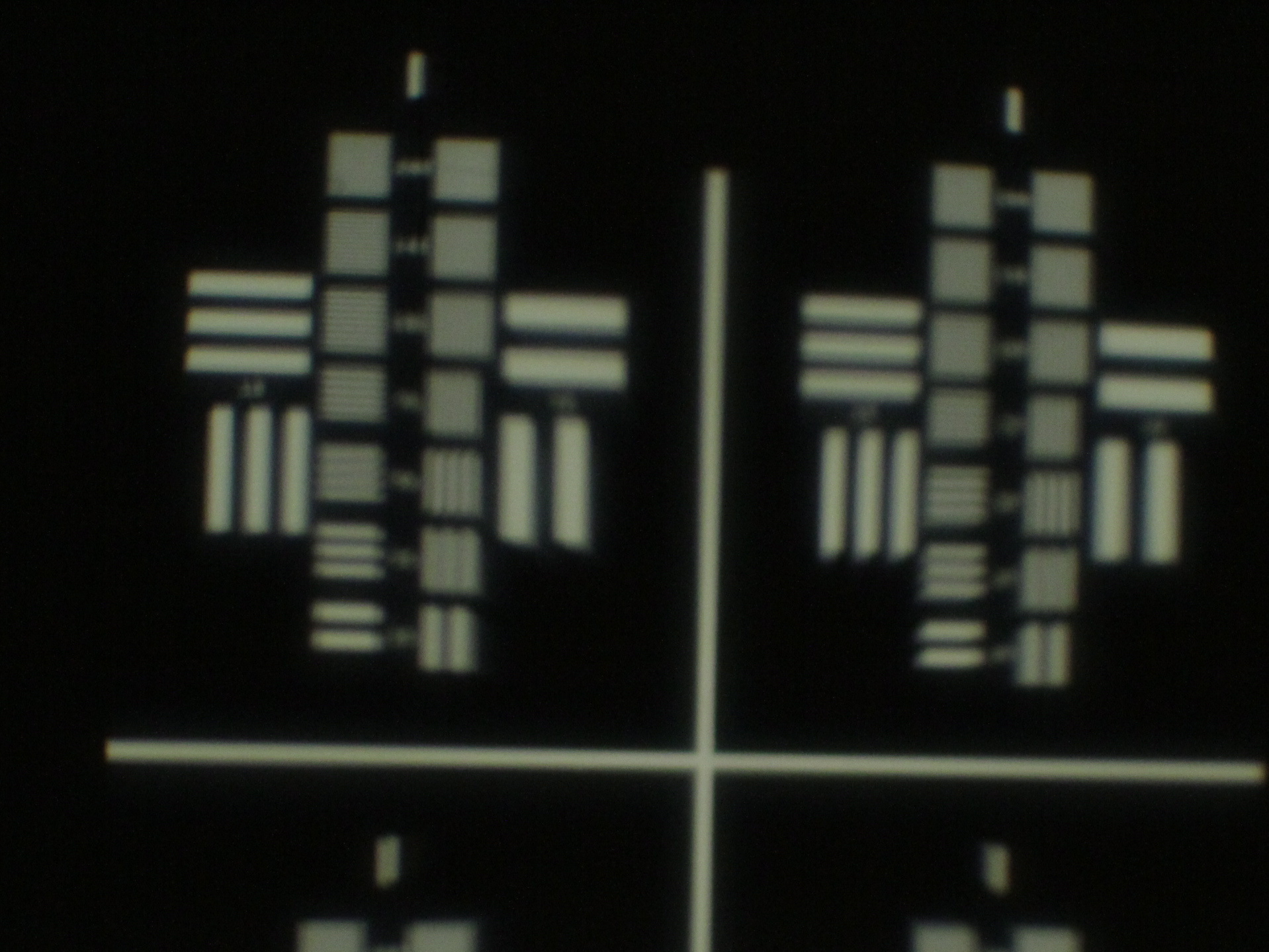
Fig. 1
The new, high optical performance lens on the left (Fig. 2) clearly resolves 200 lp/mm. But notice that the white bars at 200 lp/mm are slightly gray, not pure white as the lower spatial frequency targets from 10 lp/mm up to about 50 lp/mm. What you are seeing is the natural MTF response fall off of even the best performing lenses. Contrast at 200 lp/mm cannot be as high as contrast at 50 lp/mm. Looking at Fig. 1, our old lens again, notice that even the low spatial frequency targets at 10 and 12 lp/mm are still gray, not white. The lens tested in Fig. 1 has very low MTF, even at low spatial frequencies.
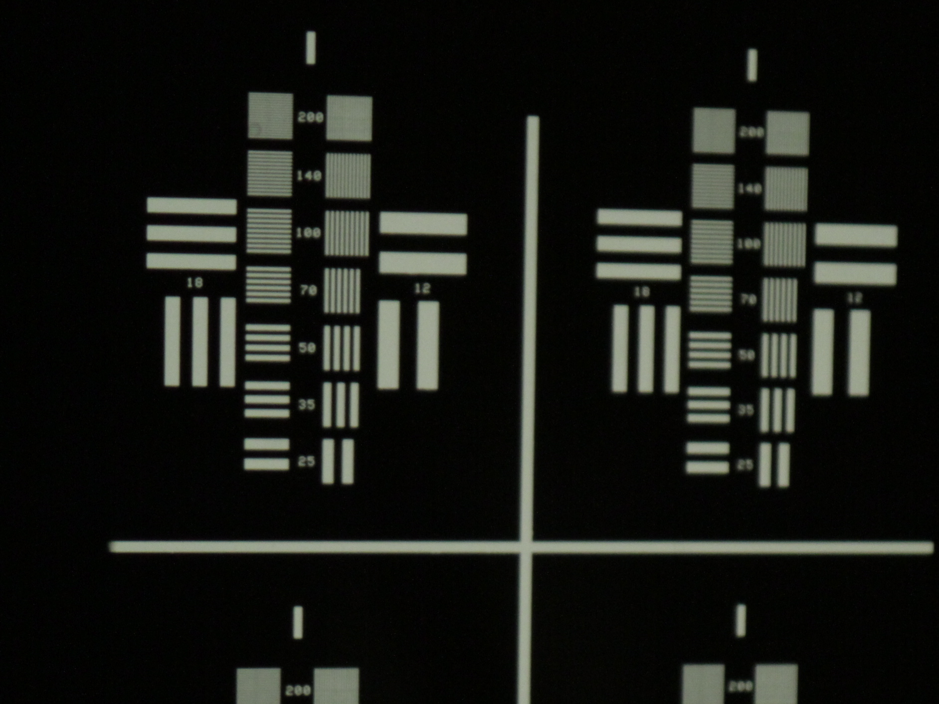
Fig. 2
So how much MTF do you need and at what spatial frequency? In the digital cine world, a good rough guide can be the pixel pitch of the camera's sensor. No sensor can record details at higher spatial frequencies than the pixel pitch (which must be divided by two since, as mentioned above, you need two pixels per cycle or line pair).
The Phantom HD Gold camera, for example, has 12.5 µm (micron) photosites (pixels), giving a pixel pitch of 80 pixels per millimeter. This corresponds to 40 cycles per millimeter. 50% MTF at 40 c/mm is good optical performance.
MTF can also be used to measure and calibrate back focus (incorrectly but commonly referred to as "collimation", but a lens cannot be collimated, only light can be collimated). The advantage of using MTF for back focus is that it will give very consistent results with a large group of test operators. Many lens manufacturers prefer it for this purpose.
MTF is a very complex subject, and this blog entry only scratches the surface. I will return to this subject in the future to explore it in more depth.

